Components
CSS-Aspen consists of the following main components:
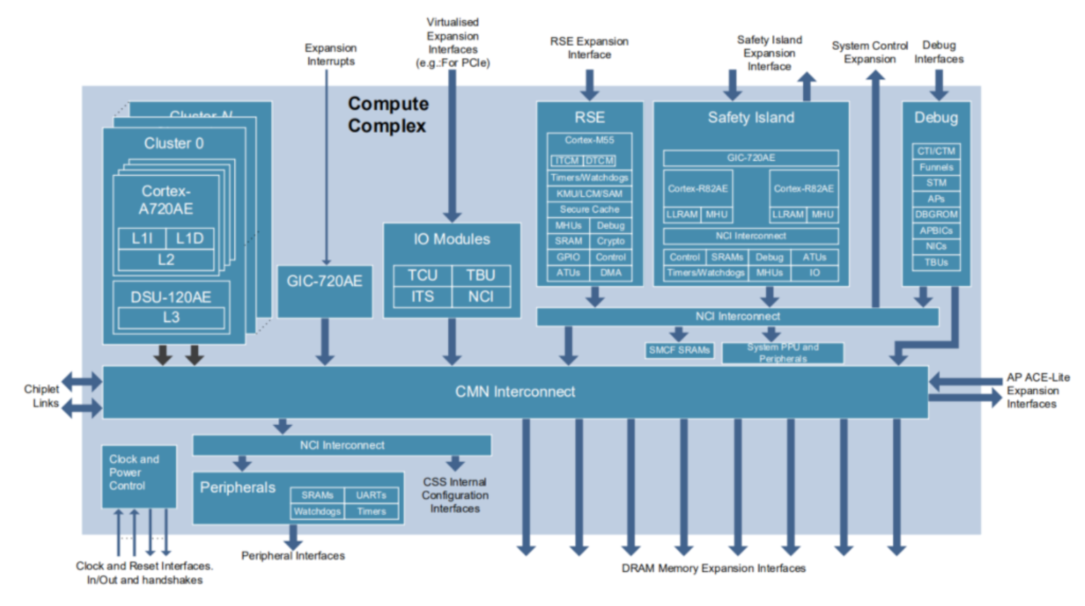
Fig. 44 System Block Diagram
System Management Block
The System Management Block (SMB) consists of the RSE Block, the Safety Island Block and the System Management Domain, as well as expansion interfaces for system management functions including SCMI services.
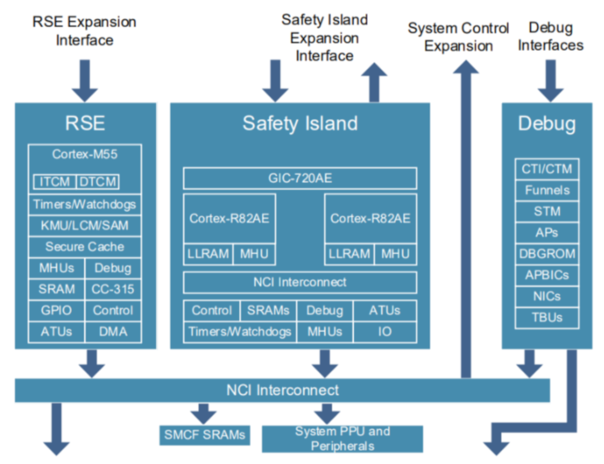
Fig. 45 System Management Block
RSE
Runtime Security Engine (RSE) is based on Cortex-M55 core and is a security subsystem fulfilling the role of Root of Trust.
See RSE Cryptography for platform which does not use the reference Arm Cryptocell cryptographic accelerator.
RSE provides an isolated Secure environment to provide security services to applications/services running in the PE Secure and Non-secure physical address spaces (PAS).
In the current software stack, RSE offers:
Secure boot, further details of which can be found in the TF-M Secure boot documentation.
The following address range in the RSE memory map provides a window into system address space:
From |
To |
Region |
|---|---|---|
0x6000_0000 |
0x6FFF_FFFF |
ATU Non-secure data access |
0x7000_0000 |
0x7FFF_FFFF |
ATU Secure data access |
Safety Island block
The Safety Island Block is a subsystem comprising of one or more Cortex-R82AE CPU clusters. The software running on the Safety Island uses the SCP-firmware framework and is responsible for power, clock and CMN control.
The number of clusters and cores depends on the chosen configuration. In the “cfg1” configuration, there is only one cluster with a single pair of dual lock-step cores. In the cfg2 configuration, there are two clusters: Cluster 0 with a pair of dual lock-step cores, and Cluster 1 with four SMP cores.
The Safety Island Block contains a GIC-720AE interrupt controller.
SCP-firmware
The SCP-firmware project provides a software reference implementation for dedicated system control processors that are used to abstract power and system management tasks away from application processors. In CSS-Aspen, the Safety Island is responsible for system management tasks, so the SCP-firmware framework is used.
In CSS-Aspen, SCP-firmware is responsible for:
PPU control of the Primary Compute
CMN interconnect configuration
Runtime services:
Power domain management
System power management
System Control and Management Interface (SCMI, platform-side)
GIC Multiple Views
The GIC has a new optional feature which is intended to be used in mixed criticality systems. This feature provides multiple programming views which can be used by multiple operating systems.
The Safety Island GIC provides 3 programming views:
View-0: Used by Safety Island Cluster 0 (SCP) at boot to configure View-1/2 for Safety Island Cluster 0/1 respectively.
View-1: Used by Operating System on Safety Island Cluster 0.
View-2: Used by Operating System on Safety Island Cluster 1.

Fig. 46 GIC Multiple Views Overview
Zephyr
Zephyr is an open-source real-time operating system (RTOS) with a small-footprint kernel, designed for resource-constrained and embedded systems. The Reference Software Stack uses Zephyr 4.1.0 as its baseline and adds support for a new board, fvp_rd_aspen_safety_island, for the CSS-Aspen FVP platform. This board reuses the existing fvp_aemv8r SoC support. Symmetric multiprocessing (SMP) is enabled on Safety Island Cluster 1 to support multicore operation.
MHUv3 Communication
The MHUv3 (Message Handling Unit version 3) facilitates communication between the Cortex-M of the RSE block running TF-M, the Cortex-A720AE running TF-A, and the Cortex-R82AE running SCP-firmware. SCMI(System Control and Management Interface) messages are transmitted using MHUv3 doorbell signals as the transport layer, with shared memory serving as the communication medium between the RSE, TF-A and SCP-firmware.
On the RD-Aspen platform, SCMI communications occur in the following scenarios:
From the RSE to the SCP-firmware to confirm the SCP-firmware has booted successfully.
From the RSE to the SCP-firmware to power on AP primary core (cluster 0 core 0).
From the RSE to the SCP-firmware to subscribe to the system power state notifications.
From the TF-A to the SCP-firmware to power on AP secondary cores.
From the TF-A to the SCP-firmware to initiate a system power down or reset.
From the SCP-firmware to the RSE to notify of a system power down or reset.
The diagram below illustrates the SCMI communication paths between the RSE, TF-A and SCP-firmware.

Fig. 47 SCMI Communication between RSE, TF-A and SCP-Firmware
The rd-aspen platform is currently implemented as downstream patches at
yocto/meta-arm-bsp-extras/recipes-bsp/scp-firmware/files/fvp-rd-aspen.
Configurations
The software can be built for two different platform configurations - CFG1 and CFG2. The main difference is that CFG2 includes an additional Safety Island Cluster (SI CL1) with 4 SMP cores. Additionally CFG2 supports GIC multi-view in Safety Island. However, the software used is identical; at runtime, it identifies the target variant and configures itself for the detected platform. Selecting the platform configuration in Kconfig is only necessary to launch the correct FVP.
System management domain
The System Management Domain (SMD) consists of shared peripherals, SRAM and an interconnect that connects the AP, RSE and SI blocks.
Primary Compute
The Primary Compute consists of four processor clusters to run a rich OS such as Linux. Each processor cluster includes four Cortex-A720AE cores and a DynamIQ Shared Unit (DSU-120AE).
The DSU-120AE with up to 32MB of L3 cache ensures core coherency, supports features such as snoop filtering, bus protection, Dual-Core Lock-Step (DCLS) and power management via Power Policy Units (PPUs). For more details, refer to DSU-120AE Technical Reference Manual.
The adjacent Interrupt Block contains a GIC-720AE interrupt controller.
Device tree
The CSS-Aspen device tree contains the hardware description for the Primary Compute. The CPUs, memory and devices are statically configured in it. It is compiled by the Trusted Firmware-A, bundled in the Trusted Firmware-A Firmware Image Package (FIP) and is used to configure U-Boot and the Linux kernel at runtime.
Trusted Firmware-A
Trusted Firmware-A (TF-A) is the initial bootloader on the Primary Compute.
For CSS-Aspen, the initial TF-A boot stage is BL2, which runs from a known
address at EL3, using the RESET_TO_BL2 compilation option. This option has
been extended for CSS-Aspen to load the FW_CONFIG for dynamic configuration
(a role typically performed by BL1). BL2 is responsible for loading the
subsequent boot stages and their configuration files from the flash containing
the FIP image, which contains:
Downstream changes - RD-Aspen
The RD-Aspen platform is currently implemented in TF-A as downstream patches at yocto/meta-arm-bsp-extras/recipes-bsp/trusted-firmware-a/files/fvp-rd-aspen.
Implement the RD-Aspen platform port.
Add device tree for RD-Aspen.
Add BL31 for RD-Aspen platform.
Add GIC 720AE model ID to RD-Aspen platform port.
Trusted Firmware-A Tests
Trusted Firmware-A Tests (TF-A-Tests) is a suite of baremetal tests to exercise the Trusted Firmware-A (TF-A) features from the Normal World.
Downstream changes - RD-Aspen
The RD-Aspen platform is currently implemented in TF-A-Tests as downstream patches at yocto/meta-arm-bsp-extras/recipes-bsp/trusted-firmware-a/files/fvp-rd-aspen/tests.
Implement the RD-Aspen platform port.
Introduce platform tests for CPU RAS.
OP-TEE
OP-TEE is a Trusted Execution Environment (TEE) designed as a companion to a Normal world Linux kernel running on Cortex-A720AE cores using the TrustZone technology. The communication between TF-A and OP-TEE, OP-TEE and Secure Partitions uses Arm Firmware Framework for Arm A-profile (FF-A) interface.
Downstream Changes - RD-Aspen
Patch files can be found at yocto/meta-arm-bsp-extras/recipes-security/optee/files/fvp-rd-aspen/ to:
Implement the RD-Aspen platform port.
Boot OP-TEE as SPMC running at SEL1.
Trusted Services
The Trusted Services project provides a framework for developing and deploying secure services for A-profile devices.
Reference software stack provides the following components.
SE Proxy SP to provide access to secure services hosted by RSE.
SMM Gateway SP as a smm-variable service provider.
See Primary Compute Secure Services for more information.
Downstream Changes - RD-Aspen
Patch files can be found at yocto/meta-arm-bsp-extras/recipes-security/trusted-services/files/fvp-rd-aspen/ to:
Implement the RD-Aspen platform port.
Support MHUv3 communication.
Support RSE communication protocol.
Support crypto and secure storage proxies for the RD-Aspen platform.
U-Boot
U-Boot is the Normal world second-stage bootloader (BL33 in TF-A) on the
Primary Compute. It consumes the HW_CONFIG device tree provided by
Trusted Firmware-A. The device tree is used to configure U-Boot and the
Linux kernel at runtime, minimizing the need for platform-specific configuration.
The implementation is based on the VExpress64 board family. Downstream patch files can be found at yocto/meta-arm-bsp-extras/recipes-bsp/u-boot/files/fvp-rd-aspen/.
Downstream changes - RD-Aspen
The rd-aspen platform is currently implemented in U-Boot as downstream patches at
yocto/meta-arm-bsp-extras/recipes-bsp/u-boot/files/fvp-rd-aspen.
Migrate
sevandwfedefinitions to common Arm headers.Armv8 Generic Timer to use event stream for
udelay.VExpress64 set the
DM_RNGproperty.
systemd-boot
systemd-boot is a lightweight UEFI boot manager. It takes over control from U-Boot and then boots Linux.
Address spaces
There are multiple address spaces in the system, each with address widths of up to 48 bits. Every component falls inside one of those regions.
System interconnects handle addresses of 52-bit width, with the top 4 bits used to distinguish between the regions. Address Translation Units (ATUs) are located in the RSE, Safety Island, and SMD. They can be configured to map a system-wide 52-bit address range into a region-local logical window, to allow data accesses from one region to another.
The system-wide regions are as follows:
From |
To |
Region |
|---|---|---|
0x0_0000_0000_0000 |
0x0_FFFF_FFFF_FFFF |
AP address space |
0x2_0000_0000_0000 |
0x2_0000_FFFF_FFFF |
SMD address space |
0x3_0000_0000_0000 |
0x3_0000_FFFF_FFFF |
RSE address space |
0x4_0000_0000_0000 |
0x4_00FF_FFFF_FFFF |
Safety Island address space |
All ATU configurations are owned by the RSE.